

The introduction of autonomous mobile robots equipped with robot arms has become commonplace in the research and development field, and is no longer rare.There are already examples of practical use in the industrial field, and in the future it is expected to be active in various fields and applications more than ever.
In this article,"A device for combining different products'I tried to summarize the process of challenging the production and assembly of.For research and development, if you are thinking about physical combination and fixing of different hardware, or prototype of original equipment, please take a look.
table of contents
Task
The challenges of this prototype challenge are as follows.Part fabrication >>> Installation >>> Verification We will carry out all of
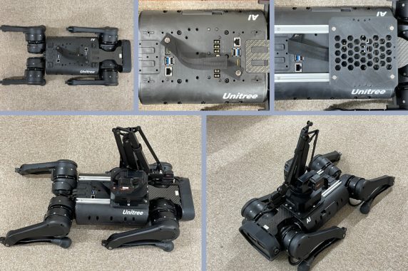
| We would like to attach another manufacturer's robot arm (Ufactory uArm) to the back of our quadruped robot (Unitree A4). There is no official manufacturer's mounting equipment, but we will prepare an original design mounting equipment so that the Ufactory uArm can be firmly fixed so that the operation of the Unitree A1 is not affected. |
Target item
In this prototype challenge, we assume that two items will be used in combination for research and development purposes, and as a test item for mounting and physically fixing the Ufactory uArm on the Unitree A2, a simple mounting device decided to create a
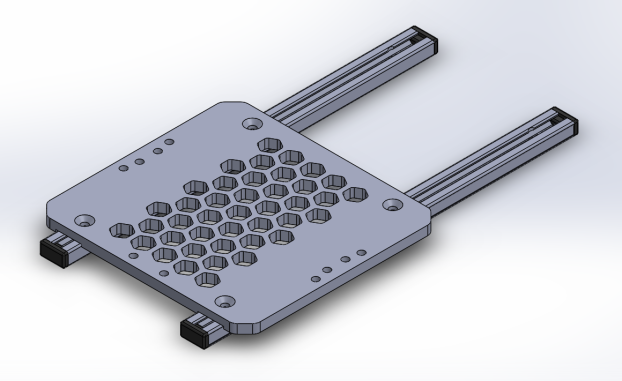
■ 3D model of mounting fixture designed in Solidworks
| Note: The prototyping/verification introduced in this article is only a simple prototyping and mechanical integration.System integration, Ufactory uArm operation, detailed evaluation, etc. have not been performed. |
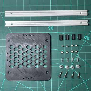
Here are the products and parts prepared for this prototype challenge.
|
[1] Quadruped robot (Unitree A4): Maximum payload of 1kg [2] Robot Arm (Ufactory uArm Swift Pro): Weight 2.4kg (without interface cable) [3] Prototype mounting hardware and fixing hardware: mounting plate, mounting rail, screws, nuts (total weight 220g) |
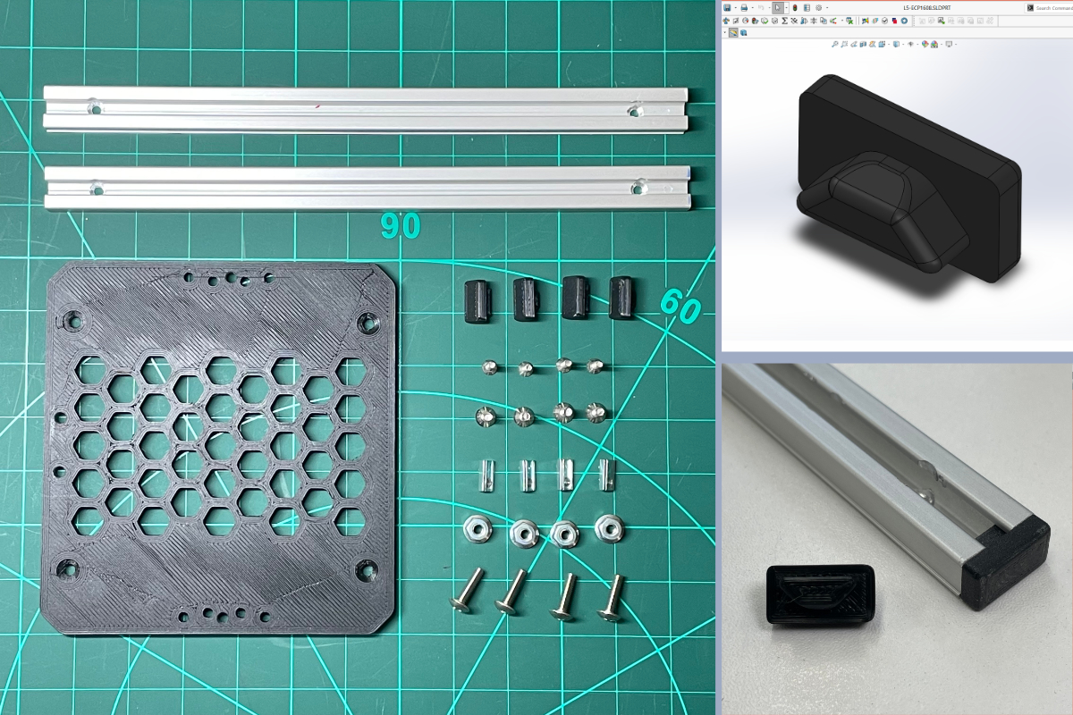
The pictures and details of the parts prepared in [3] are as follows.By combining these with [1] [2],quadrupedal robot (It is assumed that Unitree A1) can perform stable posture change and movement with the robot arm (Ufactory uArm) loaded.
|
No. |
Part name |
Part number |
Brand |
Quantity |
Remarks |
|
1 |
mount plate |
|
|
1 |
3D printer product (material PLA) |
|
2 |
Aluminum rail (16×8 strut profile 5) |
L5-SPH1608N |
had |
2 |
Additional processing of 1m purchased product: Length 240 x 2 cuts → 2 countersink holes |
|
3 |
Post-assembly nut for aluminum rail (T nut 5ST) |
5ST – L5-TST4 |
had |
4 |
|
|
4 |
End cap for aluminum frame |
|
|
4 |
3D printer product (material PLA) |
|
5 |
M4x10 countersunk screw |
|
|
4 |
|
|
6 |
M4x15 truss screw |
|
|
4 |
|
|
7 |
M4 locking nut |
|
|
4 |
|
|
8 |
M3x12 cross recessed countersunk screw |
|
|
4 |
|
Work content
The actual process wasMeasurement/Preparation >>> Design >>> Parts Fabrication and Preparation >>> Assembly >>> Operation Trialis the flow.
Below is a summary of what we did in each phase.
Phase 1. Measurement/Preparation
- Get unitree A1 mounting features and dimensions from the manufacturer (Unitree)
・Check the Ufactory uArm manual and check the fixing method and the dimensions required to install the equipment
Phase 2.Design
・3D modeling/design with CAD
I mainly designed and produced the 3D model of the mount plate.
The central part of the plate is designed with a honeycomb structure for the purpose of reducing the weight of the mounting plate itself and shortening the 3D printing time.
Also, in order to prevent tilting during assembly, a groove is provided on the bottom of the mounting plate for attaching the aluminum frame.
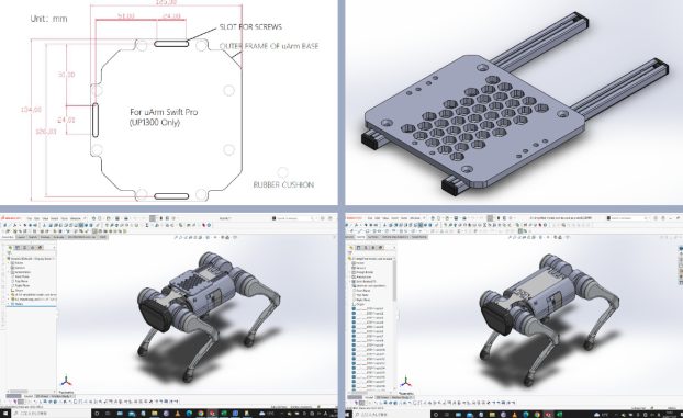
* At the time of design, I did not have the CAD data of the Ufactory uArm or the actual arm at hand, so I designed the screw holes based on the mounting dimensions described in the manual.
Phase 3. Parts production and preparation
・Output with a 3D printer and processing of each part
I printed out the mount plate and end cap with a XNUMXD printer.
Also, the size of the aluminum frame cap that I ordered was wrong, so I downloaded the CAD data for the correct size from the manufacturer's site and printed it out with a 3D printer.
・ Aluminum rail processing (length cutting, drilling)
I adjusted the length of the aluminum rail.This process is done by hand as this is a prototypal challenge.
(Tools used: saw for aluminum, electric hand drill)
Phase 4. Assembly
・Install each part prepared for Unitree A1 and Ufactory uArm
The installation procedure is as follows.Please watch along with the assembly video.
- Remove the four rubber protector parts on the top of the Unitree A1.
- Using the mounting holes of the rubber protector parts, attach the aluminum rails with M3x12 cross-recessed countersunk screws.
- Set 4 post-assembly nuts on the aluminum rail and fix the mount plate with 10 MXNUMXxXNUMX countersunk screws.
- Place the Ufactory uArm on the mounting plate and fix it with M4x15 truss screws and M4 locking nuts.
| *In this prototype, the Ufactory uArm is fixed with screws and nuts, but there is also a method of using a heat-set insert in the mounting plate to improve assembly workability. |
Phase 5. Operation trial
With the Ufactory uArm loaded, perform basic walking and posture operations of the Unitree A1
Result
The results of this prototype challenge are as follows.
|
We were able to create a fixture that is robust enough to support the weight of the Ufactory uArm. Also, when I moved the Unitree A1, I was able to operate it stably without losing its balance. |
I prepared a video of how it actually moved when assembled.You can check the movement that does not make you feel uncomfortable or unstable when standing up or changing your posture.
Summary
The mounting fixture that was prototyped with a 3D printer this time was able to withstand basic movements with the Ufactory uArm attached to the Unitree A1, and could be used without any problems.In addition, since this mounting fixture uses aluminum rails, it is possible to change the position of the Ufactory uArm along the back of the Unitree A1.
It should be noted that the Unitree A1's legs may cross and lose its balance and crash during attitude control in response to specific terrain and special forward and backward behavior. The Unitree A1 is somewhat resistant to impact, but the durability of the Ufactory uArm side is not very high, so it is necessary to operate with great care against falls and contact.
We will help you create a prototype that meets your needs.
We accept requests for the design and production of original parts using 3D printers, such as the mounting fixtures created this time.
|
・Prototyping of original instruments/attachments ・Equipment for combining different products ・Replacements for damaged or lost parts |
Please feel free to contact us if there are any situations where we may be able to help you.

|
Please feel free to use the form below to discuss the design and production of items, including 3D model production and 3D printer output.. Output examples: 3D printing (FDM), laser engraving, CNC routers, CAD (2D/3D) data, etc.
|